
ElectronAVE - Installation Instructions
FAQ and Debugging
If you have some questions about this product or you're looking to debug your installation, then you should start by reviewing our ElectronAVE - FAQ and Debug page.
Recommended Tools
This section will continue to grow in the future, but the current recommended tools are as follows:
- Soldering microscope (this is almost certainly a necessity)
- Fine pitch/small tip soldering iron
- Lead-free solder (leaded solder is OK, but proper ventilation is required)
- Solder flux
- Flux remover (isopropyl alcohol - also known as IPA).
- X-acto knife or small wire brush
- 26AWG wire (anything larger than 30AWG works well).
Installation Instructions
Right click each of the pictures below and open them in a new tab to view them at their highest resolution.
STEP 1
Determine the Revision of your Wii
Begin by determining the revision of your Wii's hardware. Reminder that this installation does not work on the Wii Mini.
The community over at BitBuilt.net have done a fantastic job at describing steps to determine the revision of your hardware found here: Wii Revision Guide.
This picture from that page is specifically useful:
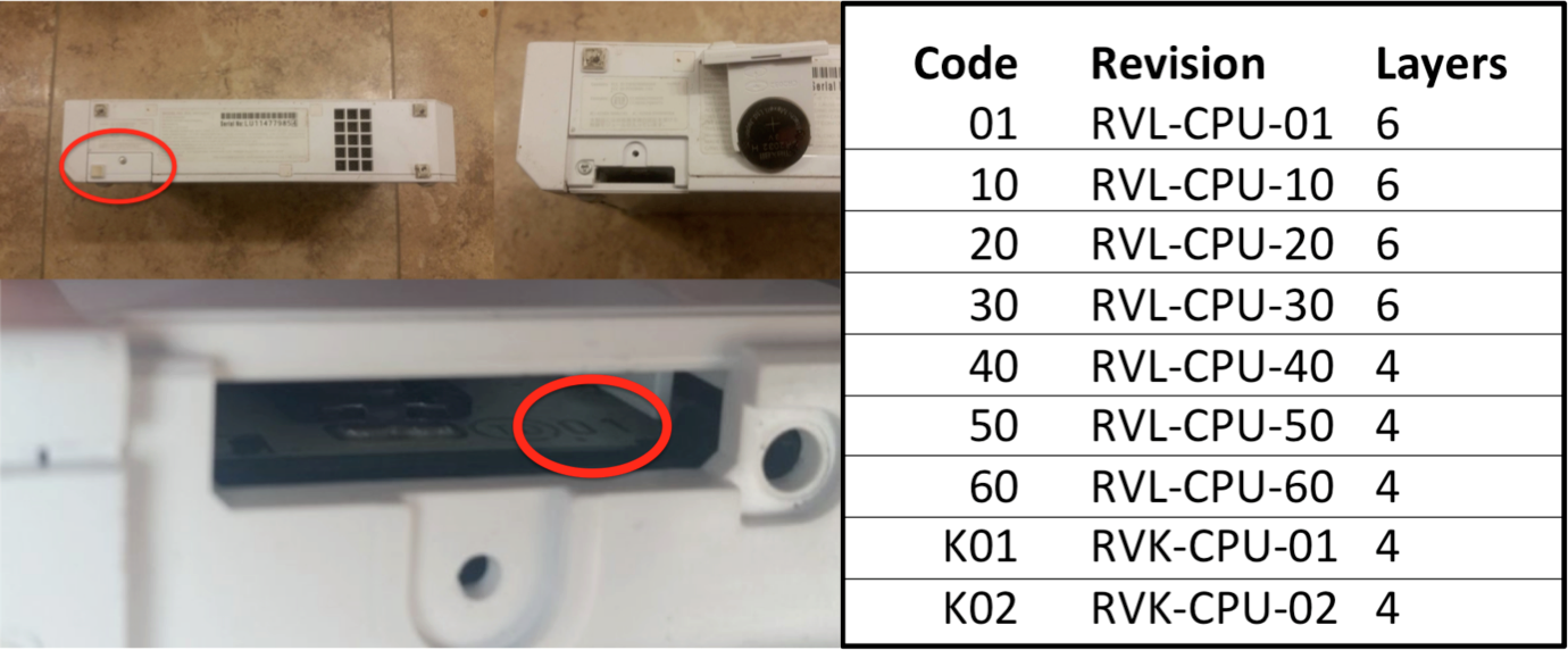
The revision of your Wii dictates where the ElectronAVE Kit will be installed on your Wii as described in the next section.
STEP 2
Disassemble your Wii
I won't write out the teardown steps in this guide as high quality instructions can be found on iFixIt here: Nintendo Wii Teardown. Reminder, you will have to do these steps in reverse to reassemble your Wii at the end of the installation.
STEP 3
Identify the vias to install the kit.
The ElectronAVE has two sets of vias to allow for the kit to be installed in every version of the Wii excluding the Wii Mini.

Revisions RVL-CPU-01 through RVL-CPU-30
Locate this grouping of vias on the bottom side of the main motherboard (Note, in these pictures there is a large missing component, that does not need to be removed for this installation).

Here you can see the vias on the ElectronAVE Kit lined up with those vias.

Revisions RVL-CPU-40 through RVK-CPU-02
Locate this grouping of vias on the bottom side of the main motherboard.

Here you can see the vias on the ElectronAVE Kit lined up with those vias.

STEP 4
Prepare the vias for installation
Once the vias have been identified, you should carefully tin the vias such that they have a small amount of solder applied. This should be done with solder flux to ease the tinning process.
Some versions of the Wii have soldermask covering the vias that are needed for installation so a fine wire brush or Xacto knife should be used to remove that soldermask prior to tinning the pads.
These steps have been shown in the subsequent pictures on a RVK-CPU-02 console, but the steps are the same for all versions.
Location of the vias:


Use an X-acto knife or wire brush to remove the soldermask from the required vias (not required for all versions of the Wii).

Apply solder flux and then tin each of the required exposed vias

STEP 5
Solder the ElectronAVE flex to your console
This step is critical and arguably the most difficult step of this installation.
Apply a small amount of solder flux over the vias that are going to be installed to your flex.

Carefully, under a microscope, align the vias of your ElectronAVE flex to the vias on the Wii. Take your time, patience is key. This is where most folks have a hard time.

Slowly go around and solder each of the vias of the flex to each of the vias of the Wii.

Using isopropyl alcohol (IPA), remove the excess flux to expose your cleanly solder vias!

Take a deep breath! The hard part is over!
STEP 6 - OPTIONAL
If you are not confident in your installation, then now would be a good time to use a multimeter to check for continuity from the Wii's motherboard to the main chip on the ElectronAVE flex.
Utilize the Signal Locations section of the FAQ and Debugging page to perform this step.
STEP 7
Solder the power wires to the flex
You can locate test points on the Wii that are marked for GND, 3.3V, and 5V.

There are matching power pins on the ElectronAVE flex.

Solder wires from each of the Wii's power pads to each of the flex's power pads. These pictures show 26AWG wires, anything above 30AWG wire will work.
Be careful to avoid running wires over the mounting hole pads on the Wii.

STEP 8
Connect the GameCube controller port and IR Sensor board to the flex
The ElectronAVE Kit runs GCVideo which has an on-screen display (OSD) that can be used to modify settings of the installation. You either need to install the included IR Sensor board and/or connect a GameCube controller port to the kit.
You can only use the GameCube controller port with Wii's that have those ports installed. If your console does not have controller ports, then you must install the IR sensor board.
GameCube Port Connection:
Solder a wire from any one of these test points (TP27-TP30) to the GCD pad on the ElectronAVE flex. Which ever GameCube port you solder to will need to be used to access the OSD menu of GCVideo, so remember which port you connect to.


IR Sensor Board Connection:
The IR sensor board gets soldered on the pins of the Wii's audio and video output connector (AV connector) as shown below.


Important Optional Step!!
You now have the option to short across two pads of the AV connector on the Wii.
- If you short these pins then the ElectronAVE Kit will be able to output a 480p resolution. But, the Composite (CVBS) output of the Wii is disabled. Component (YPbPr) is still available in this configuration and digital adapters like the ElectronWarp still work perfectly.
- If you leave these pins and do not short them then Composite, Component, and digital adapters will all work; however, the ElectronAVE Kit will be stuck in 480i output resolution. If you want 480p output from the ElectronAVE, then you can connect a Component cable or digital adapter to the Wii and then the option to output 480p via the ElectronAVE will be available.
Below you can see the two pins that have been shorted on the Wii's output connector:

You can then solder from the IR and BT test points of that board to the corresponding pads on the ElectronAVE flex.


STEP 9
Solder the output connector board
You can now solder the output connector board to the backside of the USB connectors of the Wii.


STEP 10
Connect the flat flex cable (FFC) between the output connector and the ElectronAVE
Ensure that the blue stiffener portion of the FFC is on the bottom and firmly connect it to both the output connector board and the ElectronAVE flex.


Congratulations, the installation of the ElectronAVE Kit is complete!

STEP 11
Reassemble the Wii and cut out holes for the output connector and IR sensor board
I do not currently have instructions ready for this section, but this video from Voultar perfectly explains these steps starting at 49:46.
https://youtu.be/v44PfH3R4iA?si=z-V2BdqI-isdDIXi&t=2986
STEP 12
Access the GCVideo Menu
GameCube Controller
If you soldered a connection to a GameCube controller port, then you can access the GCVideo menu by pressing and holding L+R+X+Y on the controller for a few seconds. If you do this and no menu appears, then review the FAQ and Debug page.
IR Sensor and Button
The following image is from the GCVideo github repository and shows the general screen that is available through the on-screen display.
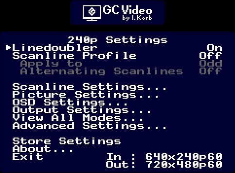
Please review the GCVideo github repository if there are specific questions with regards to the available functionality of the project.